REPLACING THE INSTRUMENT CLUSTER BULBS WITH LEDS
Even with a few burnt out bulbs, the instrument lighting was really dark and replacing them would barely help. I bought some LEDs for about $10 to brighten it up. Conveniently, someone already did the work finding the right LEDs. Thanks Ike!
Click here for an eBay link to the LEDs.
The 1984 cluster has ten bulbs and the panel dimmer still works without leaving a regular bulb installed.
Click here for an eBay link to the LEDs.
The 1984 cluster has ten bulbs and the panel dimmer still works without leaving a regular bulb installed.
I WISH IT WAS AS SIMPLE AS PLUG AND PLAY
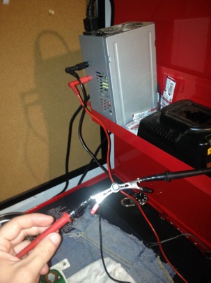
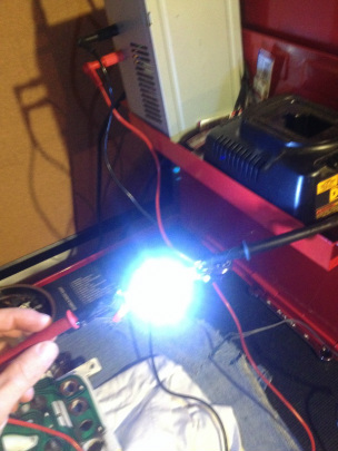
LEDs are polarity sensitive - not like regular bulbs. There is a 50/50 chance that an LED will be installed in the bulb holder and work. The problem is that there are ten bulb holders in the cluster and the chances of having them all installed with the correct polarity is slim. I tried and about half of them lit up. Plugging and unplugging the two harness in the back of the cluster is a pain, so testing and setting it up correctly is easier outside of the vehicle.
|
|
Luckily, it only takes at the most two tries to figure out the polarity of each LED. The 12 volts are being supplied from that grey box with binding clips and multimeter leads. It is a CPU power supply scrapped from an old computer. I keep it right there on my toolbox for doing things like this and it comes in handy. If you want to know how to make one, there is a link on the homepage of this website.
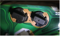
INSTRUMENT CLUSTER CIRCUIT BOARD BULB POLARITY
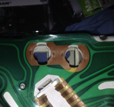
Rather then have to read a bunch of wiring diagrams and matching colored wires and pin locations, I did it the easy way. The back of the gauge cluster looks like a printed circuit. I stared at the turn signal bulb area for awhile and then realized that the left and right turn signals have one thing in common - a common ground. The brown channel between the two bulb holes is where the turn signal bulbs share the negative. The circuitry on the opposite side of the bulb holes is the individual positive for each turn signal bulb. These can be traced back to the two top pins where the connector plugs in. At least half of the bulbs share the same ground circuit which goes all around the cluster. That makes the negatives easy. The circuitry can be traced around and eventually, the polarities of all the bulb locations are known!
I marked the side of each bulb location with red and black sharpies with a + or - because I don't want to ever trace the circuits again. Since the circuits are marked, the bulbs can be tested before the instrument cluster is re-installed. Just touch the power leads to the pin locations where the connector connects to make sure there is no corrosion in the bulb holders or board. There are a few bulbs that share a ground with the tach, there is a "G" marked on that circuit. Unfortunately, I didn't realize that until I was just about done.
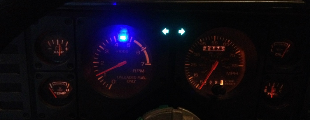
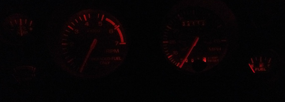
BEFORE LEDS
Notice that it had to be dark in the garage just to be able to take a picture of the gauges lit up on the highest dimmer setting.
WITH LEDS
I didn't even bother turning off the garage lights because the gauges are actually bright!