Current Calibration
Primary Jets: 0.101"
Secondary Jets: 0.095"
Primary Metering Rod: 0.073" x 0.047"
Step-Up Spring: 4" Yellow
Idle: 800 RPM
Vacuum: 19" Hg
Driver's Side Exhaust A/F: 13.3
Passenger Side Exhaust A/F: 13.3
Choked: 1100 RPM
Primary Jets: 0.101"
Secondary Jets: 0.095"
Primary Metering Rod: 0.073" x 0.047"
Step-Up Spring: 4" Yellow
Idle: 800 RPM
Vacuum: 19" Hg
Driver's Side Exhaust A/F: 13.3
Passenger Side Exhaust A/F: 13.3
Choked: 1100 RPM
EDELBROCK CARB TUNING WITH AN OXYGEN SENSOR
If you are looking for a way to maximize fuel economy or power, you will probably need to do something more than vacuum gauge readings and reading spark plugs for tuning. If better gas mileage is your goal, then tune for power instead, the increased mileage will come when the engine is producing more power and you are driving it like a grandma. Running too lean can lead to less power, increased engine temperatures, and accelerated engine wear from high temps. The extreme here is melting pistons, this is bad. Too rich of a mix can cause the excess fuel to wash oil of the cylinder walls which also leads to increased engine wear from decreased lubrication and rolling coal.
If you are set on using a vacuum gauge to tune a carburetor - the vacuum gauge alone won't get you there unless you already have the right parts in the carb. A great vacuum reading will come along with a proper air-to-fuel ratio.
If you are set on using a vacuum gauge to tune a carburetor - the vacuum gauge alone won't get you there unless you already have the right parts in the carb. A great vacuum reading will come along with a proper air-to-fuel ratio.
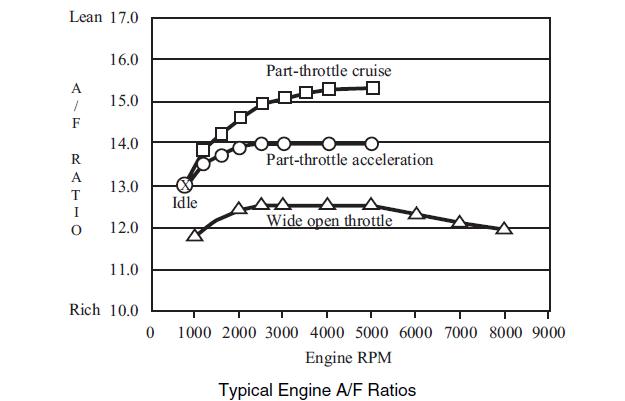
AN AIR-TO-FUEL RATIO OF 14.7 ISN'T REALLY IDEAL
Most people think that an air-to-fuel ratio of 14.7:1 is ideal. This is actual ideal for leaded gasoline and is leftover from the 1960's when manufacturers were trying to deal with emissions. Today on a performance tune it is closer to 14.2:1. Running a little lean on a fuel injected car may be fine because the ECM is monitoring and adjusting the mixture constantly so it shouldn't go dangerously lean. On a carb-ed car, you assume this responsibility as a tuner and have to deal with problems it could create.
EVERYBODY KNOWS A/F RATIO SHOULD BE 14.7! YOU'RE NUTS!
If you don't believe me, this chart below is what Edelbrock published in the Carburetor Owner's Manual. Notice how it only reaches 14.7 at about 2500 RPM during part-throttle cruise. Part-throttle cruise is probably where most engines live, so that makes sense. Since mine is a street car with more than enough power, I rarely even go above 3000 RPM. The point is if you set your A/F ratio at idle at 14.7, your going to get way lean quickly. Setting it rich will create more power, and stays on the safer side for your engine so does it really matter to be at perfect stoichiometry?
I HEARD EDELBROCK CARBURETORS ARE JUNK
I am sure you have heard that Edelbrock carbs are junk, just like you will hear that Holley, Demon, etc carbs are junk. If you are looking for a carburetor that is tuned precisely to your engine, you might as well buy an OEM carb for your particular car that is set up from the factory. My personal preference is for Edelbrock because the same basic design has been selling for more than 50 years, it's easy to tune, and reliable. Their design just makes sense to me.
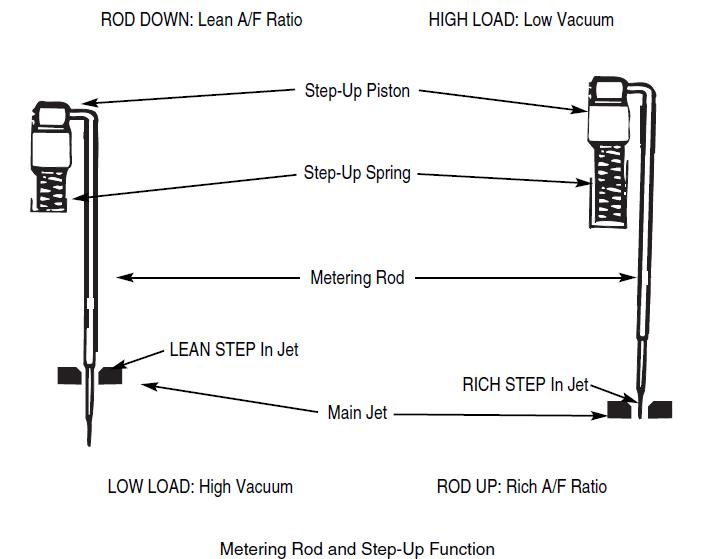
WHAT DOES ALL THIS MEAN?
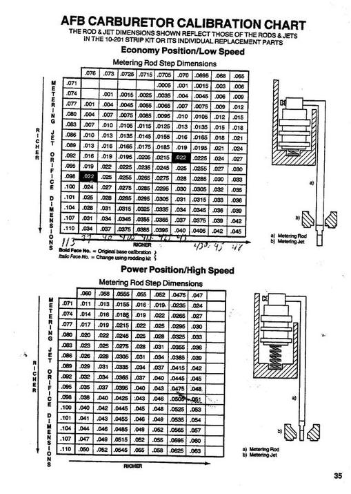
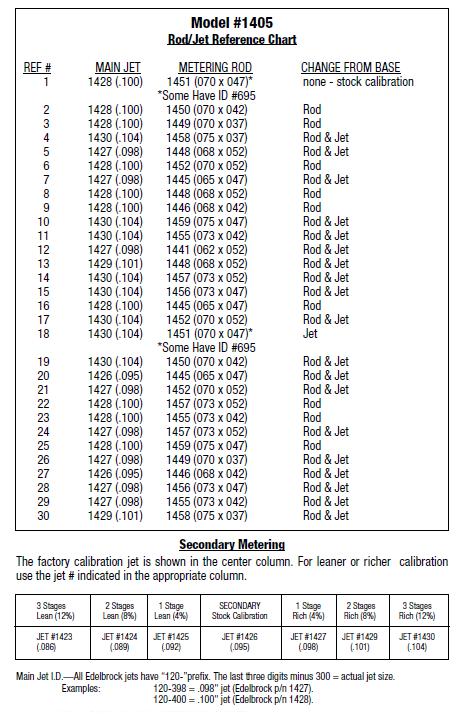
This isn't that complicated. A larger jet orifice means more fuel can pass through it. A smaller metering rod diameter means that more fuel will flow around it. The amount of fuel that the engine will get is a combination of the jet and metering rod because the metering rod is inserted into the jet. The metering rod has two diameters, one for cruise, and one for power. The rod moves up and down in the jet to change the orifice size depending on engine vacuum. The spring on the metering rod controls what level of vacuum the metering rod will move up (richen the mixture) at.
SO THE MIXTURE CHANGES BASED ON THE ORIFICE SIZE?
JET AREA MINUS THE METERING ROD AREA?
Exactly. I like things to make sense, and this is how I like to think about it. It turns out, this is how Carter (Edelbrock) used to provide charts for calibration. They didn't calculate the area, just the difference in length across the center of the jet. Thanks to David Claflin at Four Eyed Pride for scanning this.
WHAT ABOUT THE EDELBROCK CALIBRATION CHARTS?
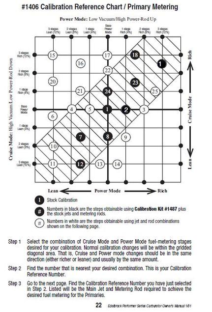
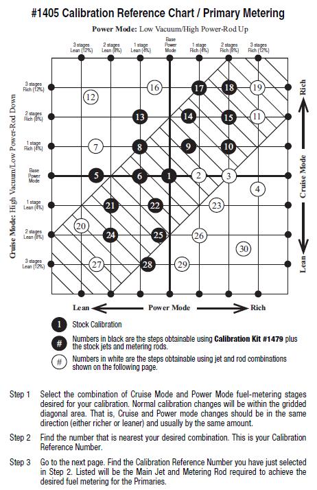
The newer calibration charts from Edelbrock are okay. I am pretty sure that the charts were generated from live testing, but if that is the case, it doesn't mean that the chart will apply to your particular setup. The thing I really didn't like about the charts is that you have to find where you want to be on the chart, then look on another page to see what jets and rods that applies to, and then go by their particular jet and rod combinations. There are some holes in the chart.
Being nerdy, I tried to find a relationship between the sizes of jets and rods and how that affected the mixture. I did find out that if only the jet size is changed, it is a straight linear relationship change on the mixture.
If the metering rod is down in cruise mode and up in power mode, it seems like they would be independent. The cruise and power stages of the metering rods are not independent of each other. I found this out by swapping rods to tune, but you can also see on the Edelbrock Calibration charts that sometimes for two metering rods with the same cruise size, it will run richer in cruise mode with a smaller power size. My best guess is that when transitioning back to cruise mode from power mode, the fuel flowing through the orifice created between the jet and rod moves at a different flow rate which can lead to a change in the mixture for some time after the power mode has ended. The metering rod diameter abruptly changes (sharp edge) between the cruise and power mode. If the rods smoothly tapered down to the power mode, it might help smooth the transition. Figuring that out would involve some "fun" incompressible flow theory which I don't care to do unless someone wants to pay me to.
|
|
|
|
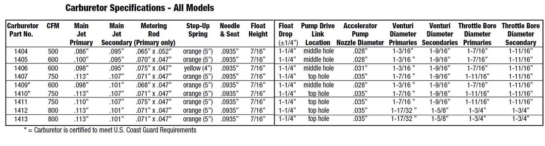
DIFFERENCES BETWEEN THE 1405 AND 1406
The actual bodies of the 1405 and 1406 are the same. The main difference is that the 1405 is tuned for power with a manual choke, and the 1406 is tuned for economy with an electric choke. Since the 1406 runs lean (smaller jets and larger rods), the accelerator pump has a larger nozzle to richen the mixture during WOT. The 1406 power mode starts later, because it is not tuned for throttle response. To make a 1405 a 1406 (besides adding or removing an electric choke), change the main jets, metering rods, step-up springs, and accelerator pump nozzles.
If you really don't know where to start tuning, for performance copy the 1405 base setting and go from there.
If you really don't know where to start tuning, for performance copy the 1405 base setting and go from there.
WHAT ABOUT SECONDARY METERING?
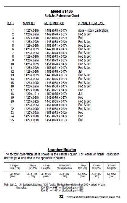
This is easy because there are no metering rods there. Go up or down a jet size. This is already on the Edelbrock Charts, but sometimes they skip a size because two jet sizes may be really close. They only do about 4% change increments in the mixture.
THE LAZY WAY TO CHANGE CALIBRATIONS
Changing jets isn't difficult, but it is a pita because you have to remove the airhorn. When you remove that cover, you are "supposed" to use a new gasket. Whenever I remove the airhorn, I end up checking float levels etc, so it takes a little time. However, changing the metering rods, takes less than a minute, so I would rather swap rods all day than swap jets.
1) Chose a jet size that makes sense and that will give you some leeway rich and lean by looking at the rod combos for that jet.
2) Install that jet, than swap the rods as necessary to get the carb running where you want it.
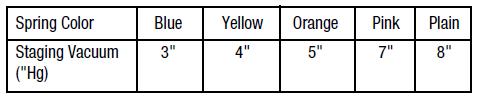
3) Once those steps are done, then test out with step-up spring works best. Since you are at this point, here's the step-up spring chart:
1) Chose a jet size that makes sense and that will give you some leeway rich and lean by looking at the rod combos for that jet.
2) Install that jet, than swap the rods as necessary to get the carb running where you want it.
3) Once those steps are done, then test out with step-up spring works best. Since you are at this point, here's the step-up spring chart:
THE CHEAP WAY TO MEASURE A/F RATIO
I USE A NARROWBAND SENSOR, IF YOUR AIR-TO-FUEL RATIO IS NOT BETWEEN ABOUT 13.2 : 1 - 16.5 : 1, YOU NEED TO EITHER USE A WIDEBAND SENSOR, OR GET YOUR CARB IN THAT RANGE BEFORE FINE TUNING.
This is a street car, so since I don't really care what my A/F ratio is outside of that range, a narrowband is fine for me. The cheapest wideband setup you can make will still be about $100. A wideband oxygen sensor functions completely different and requires a controller, otherwise the heater will burn out quickly. The controller costs almost as much as the sensor.
Besides the TYPE of oxygen sensor, many different part numbers ARE THE SAME except for the pigtail and wire length.
Bosch Reverse Engineer Oxygen Sensors
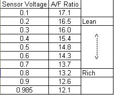
The cheapest Bosch heated oxygen sensor (4-wire) i could find was the Bosch 15123. (about $15) Since I used things I had, besides time this cost me $15. The sensor shows more values, but I only trust it between 0.2 and 0.8 volts (16.5 - 13.2)
The wiring for this sensor is:
Black Wire: Sensor Signal +
Grey Wire: Sensor Signal -
Two White Wires: Heater Power Wires (not polarity sensitive)
The heater needs a steady supply greater than 12 volts, so the vehicle battery works fine. The heater pulls a lot of amps, so as long as the vehicle is running, you won't drain the battery. A power supply will not work unless it outputs clean and consistent voltage.
The sensor signal is of the good old form:
y = m * x + b
slope = m = -5.5905
offset = b = 17.644
A/F Ratio = -5.5905 * (sensor voltage) + 17.644
If you like tables better:
This is a street car, so since I don't really care what my A/F ratio is outside of that range, a narrowband is fine for me. The cheapest wideband setup you can make will still be about $100. A wideband oxygen sensor functions completely different and requires a controller, otherwise the heater will burn out quickly. The controller costs almost as much as the sensor.
Besides the TYPE of oxygen sensor, many different part numbers ARE THE SAME except for the pigtail and wire length.
Bosch Reverse Engineer Oxygen Sensors
The cheapest Bosch heated oxygen sensor (4-wire) i could find was the Bosch 15123. (about $15) Since I used things I had, besides time this cost me $15. The sensor shows more values, but I only trust it between 0.2 and 0.8 volts (16.5 - 13.2)
The wiring for this sensor is:
Black Wire: Sensor Signal +
Grey Wire: Sensor Signal -
Two White Wires: Heater Power Wires (not polarity sensitive)
The heater needs a steady supply greater than 12 volts, so the vehicle battery works fine. The heater pulls a lot of amps, so as long as the vehicle is running, you won't drain the battery. A power supply will not work unless it outputs clean and consistent voltage.
The sensor signal is of the good old form:
y = m * x + b
slope = m = -5.5905
offset = b = 17.644
A/F Ratio = -5.5905 * (sensor voltage) + 17.644
If you like tables better:
USE A MULTIMETER OR AN A/F GAUGE, OR WHATEVER YOU HAVE
This may be cheating, but I already have National Instruments LabView and a DAC. This setup is basically a fancy multimeter with virtually unlimited programming and data processing capabilities. I copied a vi that I already had programmed for some load cells and accelerometers and made a program to read my A/F Ratio. There is an option to save the data in MS Excel for later.
National Instruments already came up with a setup for engine management, and it is very pricey. It also only runs on LSU 4.2
NI 9757 O2 Sensor Module Kit
National Instruments already came up with a setup for engine management, and it is very pricey. It also only runs on LSU 4.2
NI 9757 O2 Sensor Module Kit
IF YOU MUST USE A WIDEBAND SENSOR
You NEED a controller.
Bosch 17014 uses LSU 4.2
Bosch 17025 uses LSU 4.9
You can make your own controller using the CJ125 chip, and soldering and programming. You are probably better off going to 14point7.com and buying a kit unless you really like soldering and want to put in the time to build your own.
Bosch 17014 uses LSU 4.2
Bosch 17025 uses LSU 4.9
You can make your own controller using the CJ125 chip, and soldering and programming. You are probably better off going to 14point7.com and buying a kit unless you really like soldering and want to put in the time to build your own.
